Before an earthing system can be designed, engineers need to understand the ground it will be installed in.
Soil resistivity testing provides that information. It measures how readily electrical current can flow through the earth and helps engineers determine how fault current will disperse during abnormal operating conditions.
The results influence everything from conductor sizing to earthing layout. They also play an important role in demonstrating compliance with safety requirements for touch and step voltages.
For substations, battery energy storage systems (BESS), renewable energy projects and industrial facilities, soil resistivity testing is often one of the earliest engineering activities carried out on site.
Why Is Soil Resistivity Testing Needed?
Every site is different.
Ground conditions can vary significantly depending on soil composition, moisture content and temperature. Assumptions made during the design stage may not reflect what is actually present beneath the surface.
Testing provides site-specific data that can be used to develop an earthing system that is both safe and appropriate for the location.
The service is commonly required for:
- Electrical substations
- Battery energy storage systems
- Solar farms
- Wind farms
- Power generation facilities
- Industrial high-voltage installations
- Lightning protection projects
By understanding the electrical characteristics of the soil, engineers can make informed decisions much earlier in the design process.
How Does Soil Resistivity Testing Work?
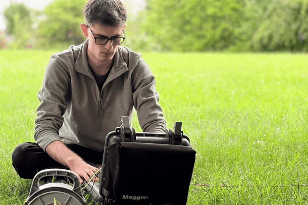
The most widely used approach is the Wenner four-pin method, which is carried out in accordance with recognised standards such as BS EN 50522.
Four electrodes are installed in a straight line at equal spacing. A current is injected into the ground through the outer electrodes while voltage measurements are taken between the inner pair.
Those readings are then used to calculate the apparent resistivity of the soil.
The test is repeated using different electrode spacings. Larger spacings allow engineers to assess conditions deeper below ground level. Once the data has been collected, it can be used to develop a representative soil model for design studies.
What Is the Service Called?
Several terms are used across the industry.
You may see references to:
- Soil Resistivity Testing
- Ground Resistivity Surveys
- Earth Resistivity Measurements
Although the wording varies, they generally describe the same process.
How Is the Data Used?
Soil resistivity testing is rarely commissioned as a standalone exercise. The results are typically used as an input to wider electrical studies.
One of the most common applications is earthing design. Engineers use the soil model to assess how fault current will flow into the ground and to determine whether safety limits can be achieved.
The information is also used within lightning protection design. Understanding how current dissipates through the earth helps engineers evaluate system performance during a strike event.
Other applications include Earth Potential Rise (EPR) assessments, electromagnetic interference studies, surge protection coordination and high-voltage system design.
Wherever current is expected to enter the ground, soil resistivity data is likely to form part of the engineering process.
When Should Testing Be Carried Out?
The best time to undertake a survey is during the feasibility stage or early design phase.
Access to accurate data from the outset helps reduce uncertainty. It also allows the earthing design to develop alongside the wider electrical design rather than being treated as a later consideration.
Testing is still valuable during detailed design work. It can also be used to validate assumptions on existing sites where ground conditions are unknown or where infrastructure has changed over time.
Turning Measurements Into Engineering Insight
Collecting measurements is only part of the process.
The data must be interpreted correctly before it can be used in design studies. This requires an understanding of earthing principles, field testing techniques and the standards that govern electrical safety.
Engineers carrying out this work often have experience in electrical power systems and earthing design. They may also use specialist modelling software such as CDEGS to develop soil models and assess system performance under fault conditions.
The quality of the final design depends heavily on the quality of the information used to create it.
Supporting Better Design Decisions
A soil resistivity survey provides more than a set of field measurements. It delivers the information needed to make informed engineering decisions.
For some projects, the results may influence conductor sizing. On others, they may affect the layout of the earthing system or highlight areas that require further investigation.
Typical deliverables include raw test data, interpreted soil models and recommendations that can be used within subsequent design studies.
By understanding site conditions early, project teams can reduce uncertainty and establish a stronger foundation for safe electrical infrastructure.
Click here to contact our team to discuss your soil resistivity testing requirements or to learn how the results can support your earthing studies and electrical safety assessments.