Introduction
A client recently commissioned Enspec to conduct a Stage 3, ENA G5/5 harmonic study for an Industrial Plant in the UK. This included a total capacity of >5MW induction machine drives, with a mixture of 6 and 12 pulse thyristor rectifiers. The drives are located at the 415V side of the various 11/0.415kV load transformers, and the site aimed to connect to the 33kV grid via a 20MVA, 33/11kV grid transformer.
The purpose of this study was to investigate the impact of the site in terms of harmonic distortions at the 33kV Point of Common Coupling (PCC) using DIgSILENT PowerFactory.
Modelling
The upstream 33kV network was modelled by an external grid and a frequency-dependent impedance. The range of equivalent Thevenin system impedances for each harmonic order from h=100Hz to h=5000Hz was provided in an impedance loci form by the Distribution Network Operator (DNO). The resolution used for the impedance loci was approximately 5000 nodes for each impedance locus. To analyse the harmonic voltages across the entire impedance loci, we used a custom-developed script in DIgSILENT.
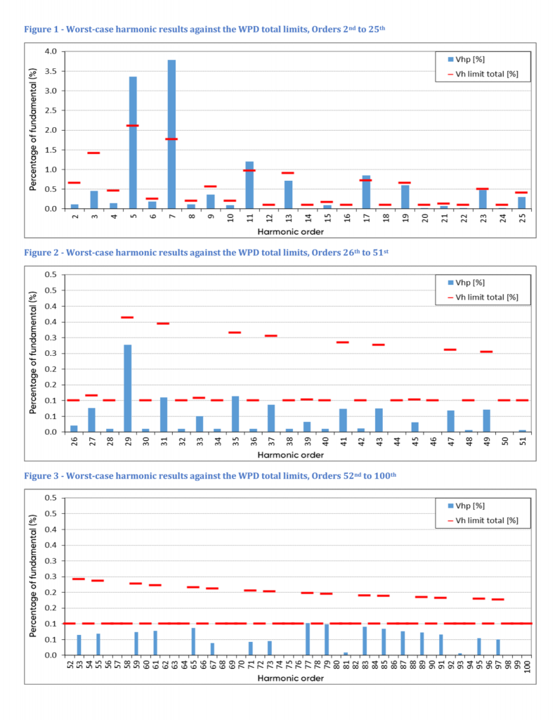
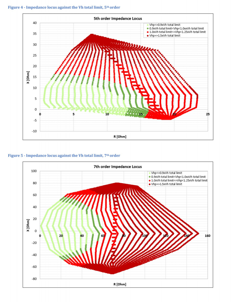
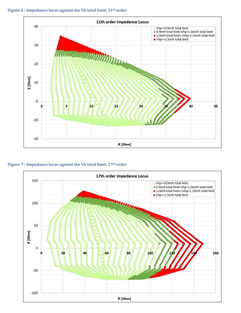
From our study, we found that the site was not compliant with the G5/5 Stage 3 limits as a result of the harmonic limit exceedances at various harmonic orders – 5th, 7th, 11th, and 17th. We also discovered that the site did not result in a considerable impedance escalation between the 2nd and 100th harmonic orders. Thus, the exceedances were caused by the incremental increase (Vhc), not by background harmonic amplification.
In Figure 1-7, we can see the worst-case harmonic voltage distortion results at the PCC against the limits specified by the DNO and the detailed voltage distortion results on the harmonic impedance locus charts for the related non-compliant harmonic orders. The various colour codes identify the level of harmonic exceedances. All results are given below.


Recommendation
In line with ENA EREC G5/5, the site required harmonic mitigation. To mitigate the high harmonics, we recommended installing either an appropriately sized passive harmonic filter or multiple active harmonic filters. A single passive filter could be designed to be connected at either the 11kV or 33kV level; however, multiple active harmonic filter installations would be required to be connected locally at the 415V level.
Based on the study outcomes and the discussions with the DNO & client, we have been commissioned to design a passive filter to be connected to the 11kV busbar to ensure G5/5 harmonic compliance. Subscribe below to be notified about Part 2, where we will show the results of the passive filter installation.
Contact us if you require any grid connection studies or for any power quality-related issues you may be experiencing.


